

Sikafloor® MultiDur ES-24 ECF
Sikafloor® MultiDur ES-24 ECF is a coloured, electrostatically conductive, low-VOC epoxy flooring system.
- Seamless surface requires minimal cleaning and maintenance
- Provides reliable and long-lasting ESD protection
- Electrostatically conductive
- Good resistance to specific chemicals
- Good mechanical resistance
- Low maintenance
- Impermeable to liquids
System Structure
Usage
Sikafloor® MultiDur ES-24 ECF is used in industrial buildings such as:- Automotive facilities
- Pharmaceutical facilities
- Electronic facilities and data centres
- Manufacturing facilities and workshops
- Logistics facilities and warehouses
- The System may only be used for interior applications.
Advantages
- Seamless surface requires minimal cleaning and maintenance
- Provides reliable and long-lasting ESD protection
- Electrostatically conductive
- Good resistance to specific chemicals
- Good mechanical resistance
- Low maintenance
- Impermeable to liquids
Colour
Available in various colour shades.
Appearance
Smooth, semi-gloss finish
System Details
CERTIFICATES AND TEST REPORTS
Sikafloor MultiDur ES-24 ECF Fire classification report
System Structure
Sikafloor® MultiDur ES-24 ECF
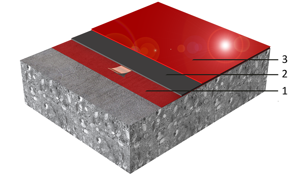
| Layer | Product | |
| 1. | Primer | Sikafloor®-161 HC |
| 2. | Conductive primer + Earthing connection | Sikafloor®-2017 Earthing Kit Sikafloor®-220 W Conductive |
| 3. | Conductive wearing layer | Sikafloor®-262 AS N |
IMPORTANT
System structure
The system structure as described in the table must not be changed.
Composition
Epoxy
Nominal Thickness
~1.0–1.5 mm
Tensile Adhesion Strength
≥ 1.5 MPa | (EN 1542) |
Reaction to Fire
Class Bfl-s1 | (EN 13501-1) |
Chemical Resistance
Laboratory-defined resistance to many individual chemicals. Before proceeding, contact Sika Technical Service for specific information.
Electrostatic Behaviour
| Resistance to ground | RG < 109 Ω |
| Typical average resistance to ground | RG < 105–106 Ω |
ECF MEASUREMENT CONDITIONS AND SPECIFICATIONS
All measurement values for the system stated in the System Data Sheet (except those referring to proof statements) were measured using the following equipment and ambient conditions:
| Condition or Equipment | Specification |
| Size of ESD-footwear | 42 (EU) (UK: 8; US: 8,5) |
| Test person weight | 90 kg |
| Ambient conditions | +23 °C and 50 % r.h. |
| Measuring device for measuring resistance to ground | Metriso 2000 or 3000 (Warmbier) or comparable |
| Surface resistance probe | Carbon Rubber electrode. Weight: 2.50 kg |
| Rubber pad hardness | Shore A (60 ±10) |
Measurement results during testing
Note: If values are lower or higher than required, carry out additional measurements about 30 cm around the point where the faulty readings are located. If the re-measured values are in accordance with the requirements, the total area is acceptable. If the requirements cannot be verified, contact Sika Technical Services.
Application
Ambient Air Temperature
Maximum | +30 °C |
Minimum | +10 °C |
Relative Air Humidity
Maximum | 80 % r.h. |
Dew Point
Refer to the individual Product Data Sheet.
Substrate Temperature
Maximum | +30 °C |
Minimum | +10 °C |
Substrate Moisture Content
Refer to the individual Product Data Sheet.
Waiting Time / Overcoating
Before applying Sikafloor®-220 W Conductive on the primer layer allow:
| Temperature | Minimum | Maximum |
| +10 °C | 17 hours | 4 days |
| +20 °C | 9 hours | 48 hours |
| +30 °C | 7 hours | 24 hours |
Before applying Sikafloor®-262 AS N on Sikafloor®-220 W Conductive allow:
| Temperature | Minimum | Maximum |
| +10 °C | 26 hours | 7 days |
| +20 °C | 17 hours | 5 days |
| +30 °C | 12 hours | 4 days |
Note: Times are approximate and will be affected by changing ambient conditions, particularly temperature and relative humidity.
Applied Product Ready for Use
Temperature | Foot traffic | Light traffic | Full cure |
+10 °C | 30 hours | 5 days | 10 days |
+20 °C | 24 hours | 3 days | 7 days |
+30 °C | 16 hours | 2 days | 5 days |
Note: Times are approximate and will be affected by changing ambient conditions, particularly temperature and relative humidity.
Consumption
| Layer | Product | Consumption |
| Primer | Sikafloor®-161 HC | 1-2 × 0.3–0.5 kg/m² |
| Earthing connection + Conductive primer | Sikafloor®-2017 Earthing Kit Sikafloor®-220 W Conductive | 1 earthing point per 200–300 m², minimum 2 per room. 0.08–0.10 kg/m² |
| Conductive wearing layer | Sikafloor®-262 AS N Filled with Sikadur 508® quartz sand (0.1-0.3 mm) | Min. 2.25 kg Binder + 0.25 kg Sikadur 508® quartz sand (0.1-0.3 mm) Max. 1.75 kg Binder + 0.75 kg Sikadur 508® quartz sand (0.1-0.3 mm) |
The filling grade varies on the air temperature at application, lower temperatures require less filling.
Note: Consumption data is theoretical and does not allow for any additional material due to surface porosity, surface profile, variations in level, wastage or any other variations. Apply the Product to a test area to calculate the exact consumption for the specific substrate conditions and proposed application equipment.
APPLICATION
ESD CONDUCTIVITY MEASUREMENTS
Recommended number of conductivity measurements is specified in the following table:
| Ready applied area | Number of measurements |
| < 10 m² | 6 |
| ≥ 10 m² and < 100 m² | 10 to 20 |
| ≥ 100 m² and < 1000 m² | 50 |
| ≥ 1000 m² and < 5000 m² | 100 |
If the measurements yield values that are outside of the agreed specification, follow these steps:
- Carry out one additional measurement within a radius of approximately 30 cm around the original measuring point.
If the value of the new measurement meets the agreed specification, the original measurement can be disregarded.
If the value of the new measurement does not meet the agreed specification, repeat the measurement described above until the fulfilment of the requirements have been verified.
If the requirements cannot be verified, contact Sika Technical Services.
INSTALLATION OF EARTHING POINTS
Refer to Sika Method Statement: Sika Method Statement — Sikafloor® mixing and application
Number of earthing connections per room: Minimum of 2 earthing connections. The optimum number of earthing connections depends on the local conditions and must be specified on drawings or other contract documentation.